Flexible PCB Manufacture: A Practical Guide for Engineers and Product Teams
- Aug 10
- 5 min read
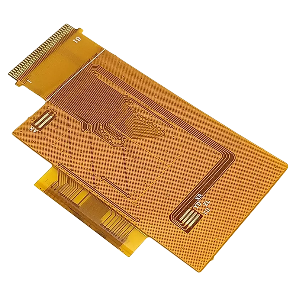
Every time a smartwatch bends around a wrist without breaking a circuit, or a drone shrugs off constant vibration without a connector shaking loose, flexible pcb manufacture is doing the work behind the scenes. Flexible printed circuit boards let designers route electronics through spaces that flat, rigid boards can't reach — hinges, curved enclosures, tight folds, anything that moves.
For engineers moving from rigid PCB design into flex for the first time, the learning curve isn't just "the substrate bends now." Flexible pcb manufacture involves different materials, different tolerances, and different failure modes than standard board fabrication. Getting it right the first time saves you from watching a prototype crack on the third flex cycle.
This guide covers what flexible pcb manufacture actually involves — materials, process steps, common design mistakes, and how to pick a fabricator who genuinely knows flex work.
What Flexible PCB Manufacture Actually Means
A flexible PCB swaps the rigid fiberglass base (FR4) used in standard boards for a thin, bendable substrate — almost always a polyimide film. Copper traces are bonded to this film rather than etched onto rigid laminate, which lets the finished board bend, fold, or roll repeatedly without the copper cracking.
Flex boards generally fall into a few categories:
Single-sided flex – one copper layer, used for simple point-to-point connections.
Double-sided flex – two copper layers with plated through-holes connecting them.
Multilayer flex – three or more layers for higher routing density.
Rigid-flex – rigid sections joined by flexible sections in one continuous board, removing the need for separate connectors between boards.
Rigid-flex is worth calling out on its own because it's become common in devices where both space and reliability matter — medical implants, avionics, compact consumer electronics — since it eliminates the connector as a point of failure.
Why Choose Flex Over Rigid PCBs
Flexible pcb manufacture isn't just about bending. It solves several engineering problems at once:
It saves space and weight. A flex circuit can replace a wire harness and its connectors entirely, which matters in wearables, aerospace, and anywhere enclosure volume or weight is limited.
It holds up better under movement. A wire harness eventually fatigues at connection points. A flex circuit built with the right copper and bend radius is designed to handle repeated flexing across the product's lifespan.
It tightens up signal routing. Controlled, laminated traces reduce the loose wiring and connector noise that can degrade signal integrity in dense assemblies.
It lets electronics follow the enclosure shape, instead of forcing the enclosure to be built around a flat board.
The tradeoff is cost. Flex manufacturing needs specialized materials and tighter process control than rigid fabrication, so per-unit cost runs higher — a fair exchange for the reliability and space savings in the right application.
Materials That Determine Flex PCB Performance
The material choices in flexible pcb manufacture affect performance far more than most first-time flex designers expect.
Substrate: Polyimide vs. PET
Polyimide (commonly known by the trade name Kapton) is the standard substrate for flex circuits because it withstands soldering temperatures, resists chemicals, and holds up through repeated bending. PET substrates are cheaper but can't survive soldering heat, so they're mostly limited to static applications like membrane switches rather than true dynamic flex circuits.
Copper: Rolled Annealed vs. Electrodeposited
This decision affects board life more than it might seem:
Rolled annealed (RA) copper has a grain structure running parallel to the foil, giving it much stronger fatigue resistance under repeated flexing. It's the standard for any dynamic flex application.
Electrodeposited (ED) copper is cheaper but has a vertical grain structure that cracks sooner under repeated bending — fine for static, single-bend uses, risky for anything meant to flex continuously.
Specifying ED copper on a board that needs to flex thousands of times over its service life is a common and costly mistake.
Adhesive vs. Adhesiveless Construction
Traditional flex laminates bond copper to the polyimide using an adhesive layer. Adhesiveless construction bonds copper directly to the substrate, producing a thinner, more flexible board with better heat resistance. It costs more but is usually the better choice for high-reliability or high-density designs.
The Flexible PCB Manufacturing Process, Step by Step
Every fabricator has its own process details, but flexible pcb manufacture generally follows this sequence:
Material preparation – the polyimide substrate is cleaned and inspected before lamination.
Copper lamination – copper foil is bonded to the substrate, either with adhesive or direct deposition.
Circuit imaging – photoresist is applied and UV-exposed using the circuit pattern from the Gerber files.
Etching – unwanted copper is chemically removed, leaving the finished trace pattern.
Drilling and plating – holes are drilled and plated to connect layers on double-sided or multilayer boards.
Coverlay application – a flexible polyimide coverlay is laminated over the circuit in place of standard solder mask, protecting traces without restricting flexibility.
Stiffener attachment – rigid stiffeners are bonded at connector or component locations for mechanical support, while the rest of the board stays free to flex.
Electrical testing – every board is checked for shorts and continuity.
Final routing – boards are cut to shape, often with a die or laser for precision on irregular outlines.
The coverlay step deserves attention, since it's a common source of long-term failure. Flex boards need a coverlay that flexes with the board rather than a rigid solder mask that cracks under repeated bending — getting the thickness or adhesive wrong here tends to show up months later as intermittent trace failures, not at initial test.
Design Mistakes That Cause Manufacturing Headaches
Even engineers experienced with rigid PCB design run into flex-specific problems.
Ignoring bend radius limits. A bend radius that's too tight concentrates stress directly on the copper. Most fabricators recommend a minimum bend radius of at least 10 times the board thickness for static use, and considerably more for dynamic flexing — ignore this and the board's usable life drops fast.
Routing traces across the bend instead of along it. Traces running parallel to the fold line handle stress far better than traces crossing it at an angle.
Placing vias or pads inside the flex zone. Any rigid feature — a via, a pad, the edge of a stiffener — becomes a stress concentration point. Keep these in static areas of the board, not in sections meant to bend.
Underestimating trace width for current load. Flex circuits often use thinner copper than rigid boards, so the same current draw generates more heat. Current-carrying calculations need to reflect the actual copper weight specified, not rigid-board assumptions.
Skipping a DFM check before production. Flex tolerances differ from rigid board tolerances. A layout that looks fine on screen may not be manufacturable at the yield or cost you're expecting without an early design-for-manufacture review.
Picking a Manufacturer for Flexible PCB Manufacture
Not every PCB fabricator handles flex well — it requires different tooling and process control than rigid board production. Before committing to a supplier, it's worth asking:
Do they produce flex and rigid-flex in-house, or subcontract part of the process?
What copper types and substrates do they stock, including adhesiveless options?
Will they run a DFM review and provide flex-specific design rules before production starts?
Can they share flex-cycle testing or reliability data for boards similar to your application?
Have they built boards with your specific bend requirements — static, dynamic, or repeated folding?
A fabricator that mostly builds rigid boards and treats flex as an occasional job often lacks the process discipline needed for high-reliability work, regardless of how competitive their quote looks.
Key Takeaways
Flexible pcb manufacture is its own discipline, not rigid board fabrication done on a bendable material. Substrate choice, copper type, coverlay design, and bend radius all have a direct, measurable effect on how long the board survives real-world use — and getting any of them wrong tends to show up as a field failure rather than a test failure.
If you're moving a design from rigid to flex, bring your fabricator into the conversation before the layout is finalized. Flex design rules vary between manufacturers, and a short DFM discussion early on is far cheaper than a respin after the first batch fails flex testing.